RailwayMiniatures
- Dwg
- BK-01
- For
- Soudamini Instruments · for an Indian Railways training institute
- Role
- Design Intern
- Tools
- CATIA V5 · AutoCAD · CNC laser cutting · Resin 3D printing
- Year
- 2026
- Result
- Built for rail training
Brief
Scaled teaching models of Indian Railways bogies and bridges, from engineering drafts to finished miniatures.
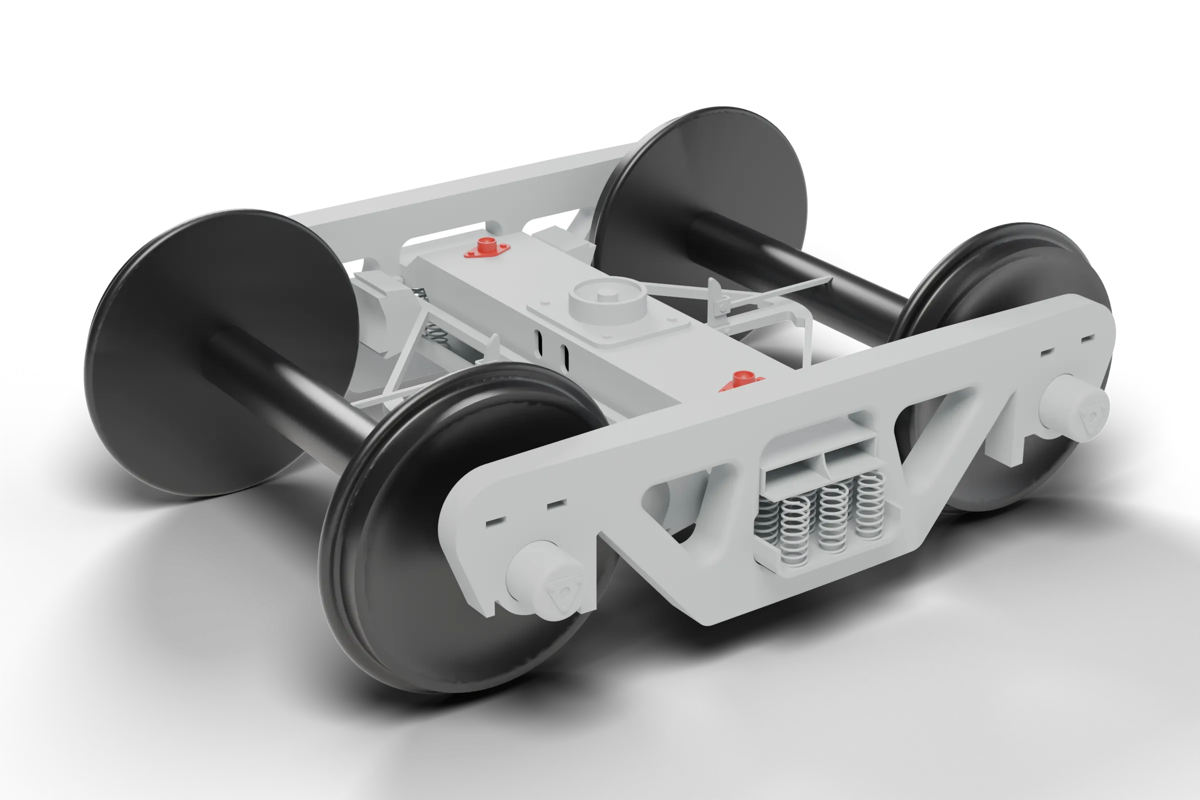
A set of large teaching miniatures for an Indian Railways training institute: two bogies — the ICF passenger bogie and the CASNUB freight bogie — and three girder bridges. As design intern at Soudamini Instruments, Bhakti modelled all five in CATIA V5, scaled them by hand calculation, drew the fabrication drawings and carried the parts through laser cutting, resin printing and finishing.
The brief
An order of 6–7 large models for a railway training institute: bogie frames and bridges built "as per specifications", with completion due by 15 May 2026. The models are teaching aids, so proportions and part relationships had to match the real hardware closely enough for trainees to identify each component.
The objects
The ICF all-coil bogie has run under Indian Railways passenger coaches since 1965. The CASNUB — cast steel friction snubber — bogie carries freight wagons such as the BOXN, with a 22.9 t axle load, 2000 mm wheelbase and 1000 mm wheels. The bridges cover three girder types: Plate Girder, Bowstring and Through Girder.
Constraints
Inputs were engineering drafts of full-size hardware, not model drawings. Every dimension had to be scaled down by hand, then assigned to CNC laser cutting or resin printing. Parts from both had to align and fasten in a single assembly.
- 01ModelAn ICF coach bogie, modelled in CATIA V5.
- 02ExplodeFrame, wheels, axle boxes and springs — each a separate solid.
- 03AssembleWheel centres and bolster alignment, set from hand calculations.
Calculate
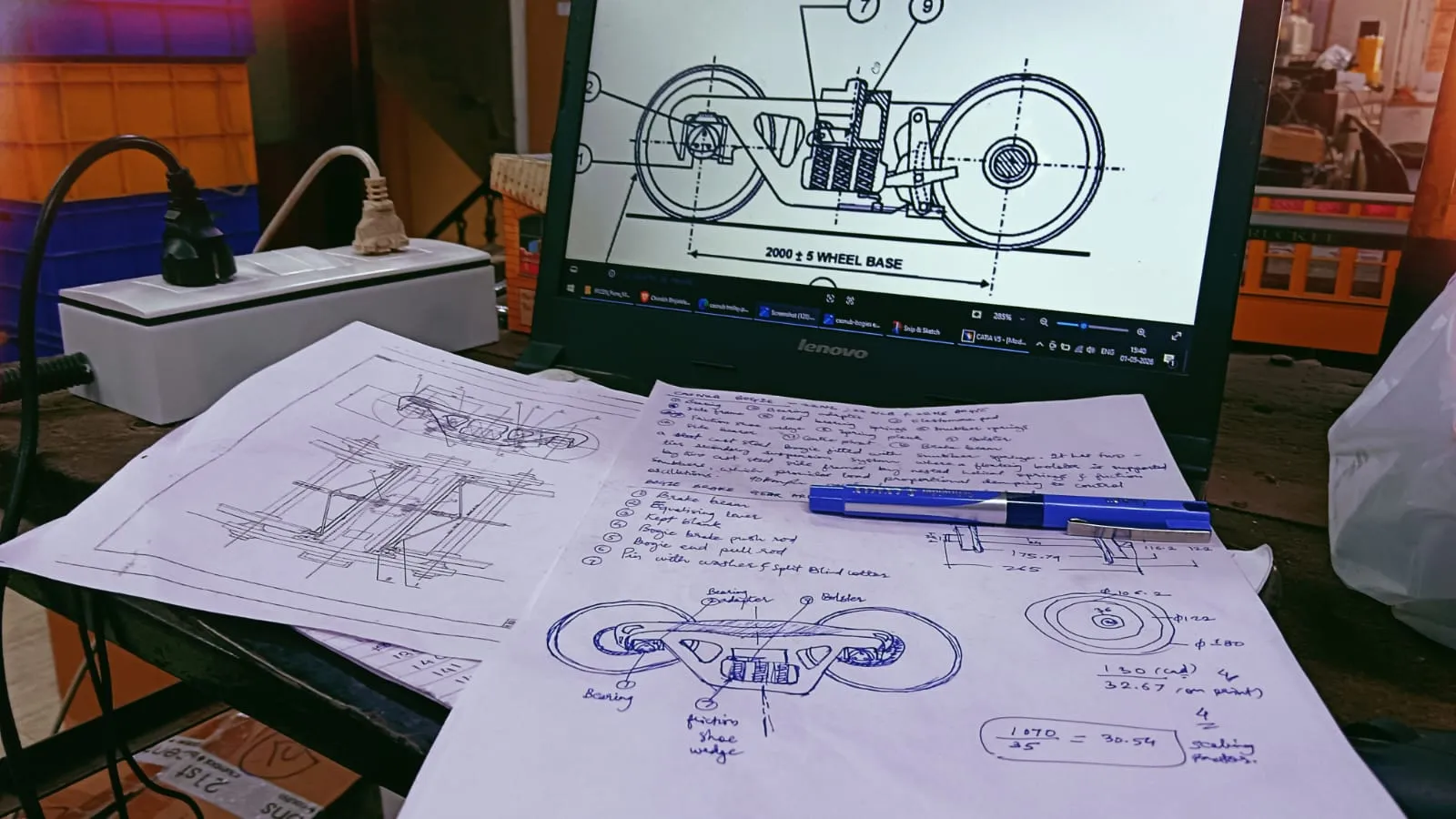
Every model started on paper. Read the reference drawings — the CASNUB general arrangement gives a 2000 ± 5 mm wheelbase — then worked out scale factors by hand (1070 / 35 ≈ 30.5) and cross-checked CAD against print sizes. Wheel-centre distances and bolster alignment were fixed here, before any CAD, alongside annotated sketches of the side frame, bolster and friction-shoe wedge.
Model
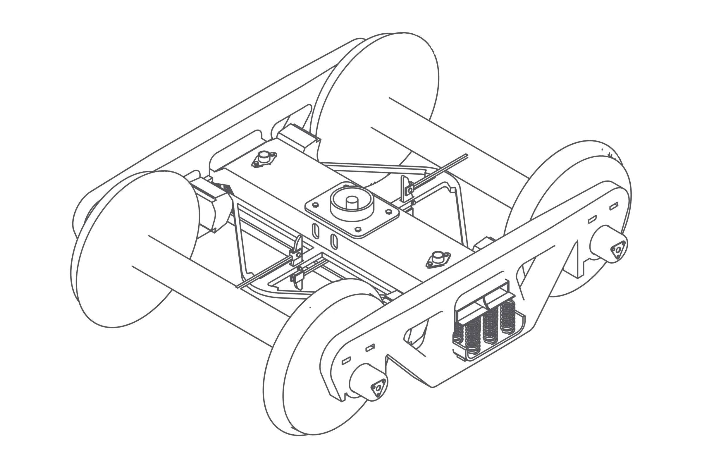
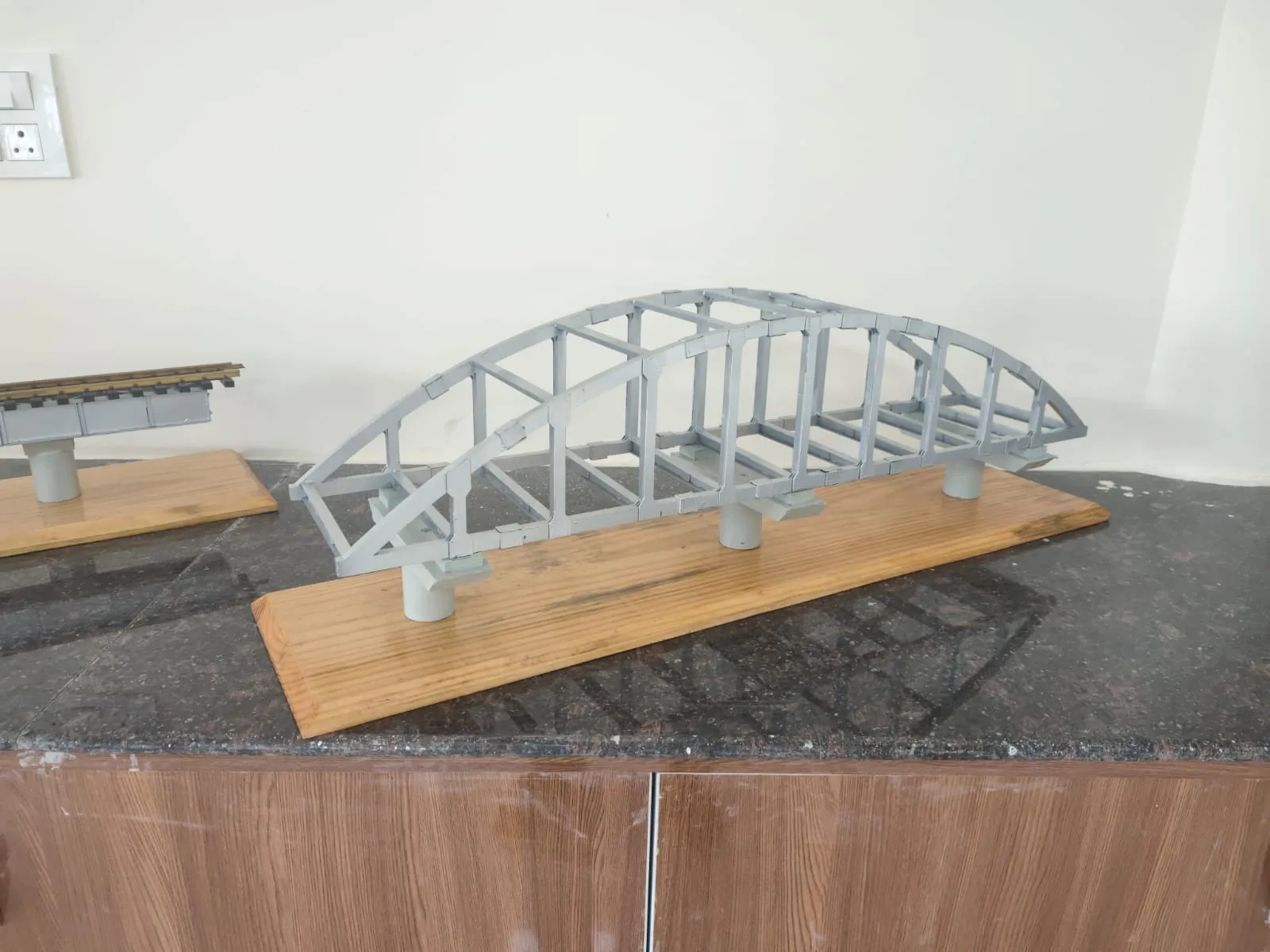
Modelled both bogie underframes and all three bridges in CATIA V5 (V5R19) from the supplied engineering drafts. The ICF bogie came to 32 separate solids; the CASNUB to 44, including 18 coil springs in its spring nests. The bridges — Plate Girder, Bowstring and Through Girder — were each scaled to a 3 ft model.
Fabricate
Turned the CAD into 2D AutoCAD profiles for CNC laser cutting, then ran the rest of the line: resin 3D printing, UV post-curing and surface puttying. Holes were drilled and threads cut on a drilling machine and a gear-tapping machine, so laser-cut and printed parts could be assembled into one model.
Finish
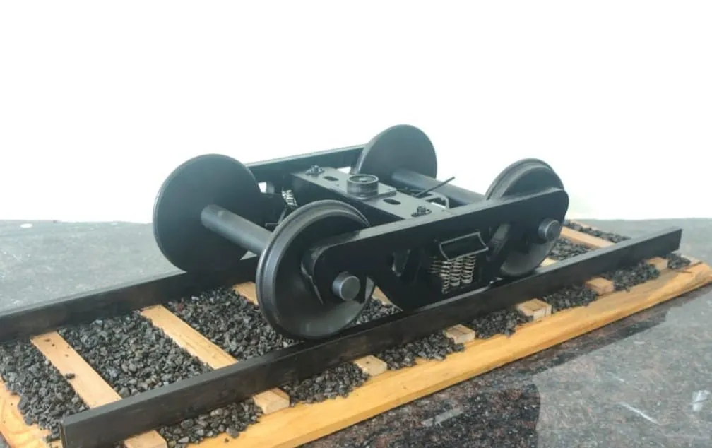
Finished bogies were mounted on ballasted track bases as teaching pieces. Each model reads the same way as the real assembly: on the CASNUB, a floating bolster sits on two cast-steel side frames through nested helical springs and friction snubbers; the ICF carries its load on all-coil springs. Trainees can trace each load path by eye.
Specification
(08)- Models
- ICF and CASNUB bogies; Plate Girder, Bowstring and Through Girder bridges
- CAD
- CATIA V5 (V5R19); AutoCAD for 2D fabrication drawings
- CAD part count
- ICF 32 solids · CASNUB 44 solids
- Bridge models
- 3 ft each
- Scale factor (worked by hand)
- 1070 / 35 ≈ 30.5
- Reference wheelbase
- 2000 ± 5 mm (CASNUB drawing)
- Processes
- CNC laser cutting · resin 3D printing · UV post-curing · puttying · drilling · tapping
- Order
- 6–7 large models, due 15 May 2026
Problems solved
Full-size drafts, miniature output
The drafts described real bogies, so nothing could be modelled straight from them. Scale factors, wheel-centre distances and bolster alignment were calculated by hand first. Fixing those numbers before CAD kept wheels, side frames and bolster in register across both bogies.
Detail density on the CASNUB
The CASNUB carries far more parts than the ICF: 44 solids against 32, including 18 coil springs in its spring nests. Each spring, bearing adapter and side bearer was modelled as its own solid, so the finished assembly reads part by part.
Two processes, one assembly
Laser-cut profiles and resin-printed parts had to meet cleanly. UV post-curing and puttying brought printed surfaces to finish; drilling and gear tapping added the holes and threads that fastened the parts together. Running all steps as one workflow kept fits consistent from model to model.
My part
- Modelled the ICF and CASNUB bogies and three bridges in CATIA V5
- Drew the 2D fabrication drawings in AutoCAD for CNC laser cutting
- Calculated wheel-centre distances and bolster alignment for both bogie underframes
- Combined laser cutting, resin printing, UV curing and puttying in one workflow
Takeaways
- Hand calculations before CAD prevent dimensional errors that are expensive to fix after printing.
- Choosing laser cutting or printing per part is a design decision, not a shop-floor one.
- A teaching model must make the load path readable, not just look accurate.