BAJASteering
- Dwg
- BK-03
- For
- Team Zenith · BAJA SAE
- Role
- Core member, steering
- Tools
- Ackermann geometry · Force calculations · TIG welding
- Year
- 2024–25
- Result
- Steering assembly
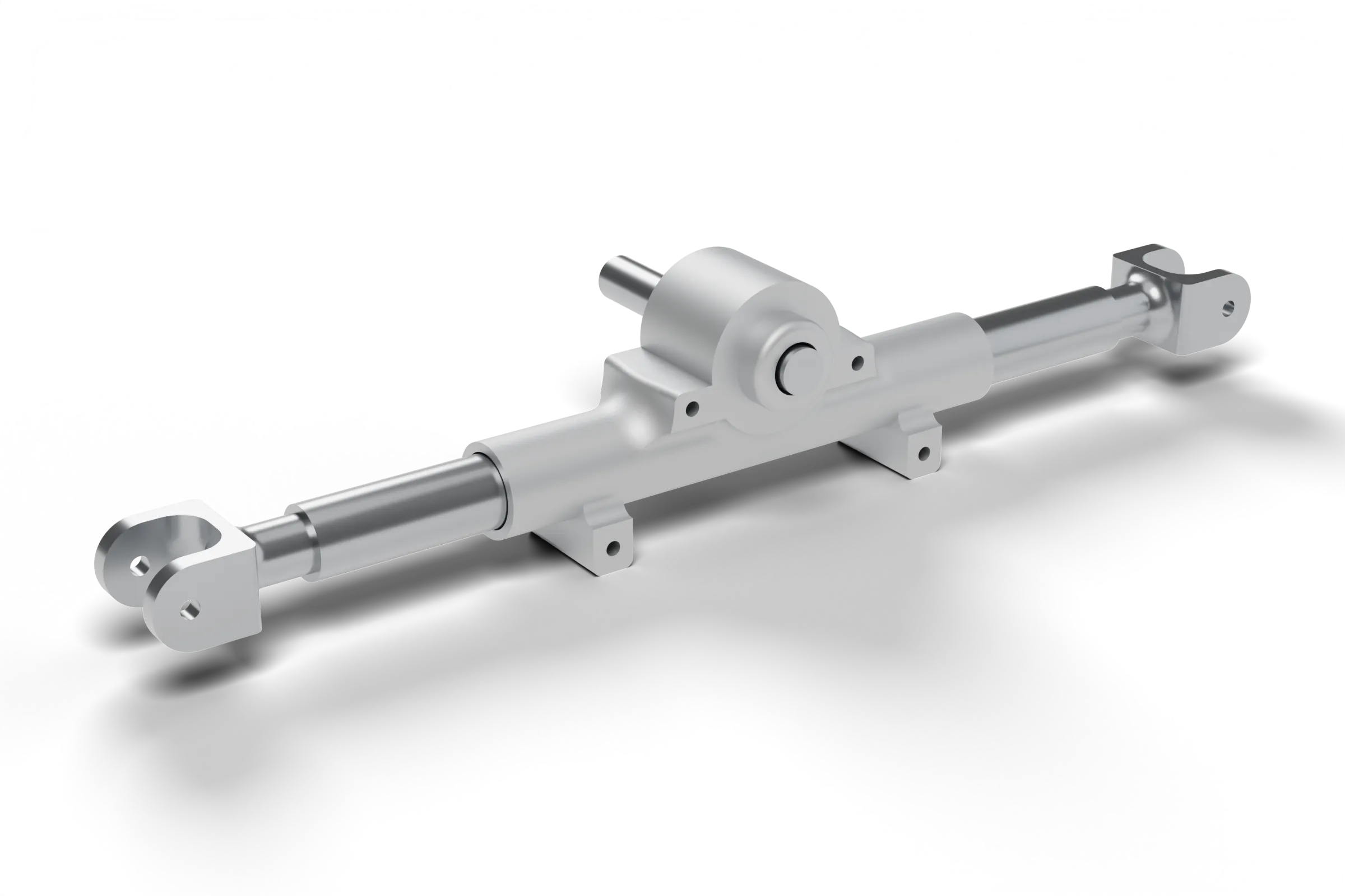
Brief
Steering for an all-terrain vehicle: rack-and-pinion, Ackermann geometry, checked by load calculations.
The steering system for Team Zenith’s BAJA SAE all-terrain vehicle — a single-seat off-road car built by students. As a core member, Bhakti designed the rack-and-pinion steering on Ackermann geometry and ran the steering-effort and cornering-force calculations that validated it. She also supported failure-theory-based ATV dimensioning, TIG welding and chassis fabrication.
The brief
Steer an off-road vehicle with a 56 in (1.4224 m) wheelbase and a 50.5 in front track, carrying 180–245 kg with the driver. The system had to turn tightly over rough ground, take bump and cornering loads, and keep steering effort manageable for the driver.
Why Ackermann
When a car turns, each front wheel runs on a different radius. If both steer to the same angle, one tyre scrubs sideways. Ackermann geometry steers the inner wheel further than the outer so both axes meet at one turning centre — less tyre scrub and a cleaner turn.
Loads to design for
The load sheet used a 44 / 56 front–rear weight split, 6.5 m/s² deceleration, μ 0.7 and a 0.4064 m CG height. It checked braking load transfer, cornering forces at 11.11, 15.278 and 16.667 m/s on a 1.7 m radius, and a 3 mg bump case.
Geometry
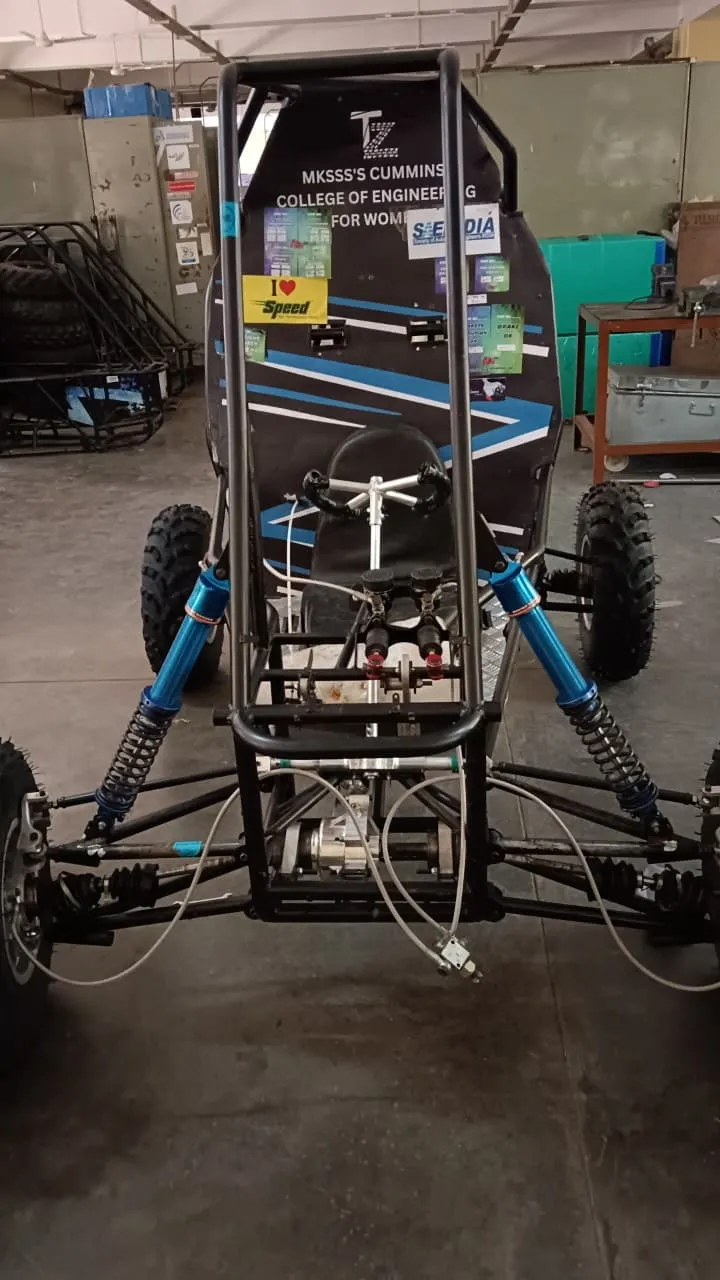
Designed a rack-and-pinion steering system laid out on Ackermann geometry. In a turn the inner wheel follows a tighter circle than the outer, so it must steer through a larger angle; Ackermann linkage geometry does this, pointing both front wheels at a common turning centre and reducing tyre scrub.
Loads
Calculated steering effort and cornering forces to validate the subsystem before fabrication. The load sheet covers braking, cornering and 3 mg bump cases across 180–245 kg with driver, at 6.5 m/s², μ 0.7 and a 0.4064 m CG height. At 245 kg, 11.11 m/s and a 1.7 m turning radius, total cornering force comes to about 12,670 N.
Build
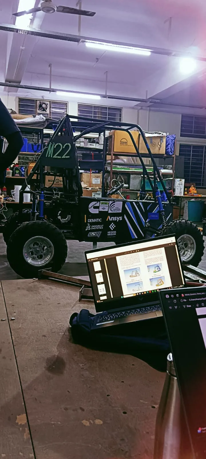
Supported the ATV dimensioning work using failure theories, then moved to the shop floor for TIG welding and in-house chassis fabrication. Off the shop floor, ran factory visits and sponsorship campaigns across MIDC industrial areas to secure components and resources for the vehicle build.
Specification
(07)- Steering gear
- Rack and pinion, Ackermann geometry
- Wheelbase
- 56 in (1.4224 m)
- Track
- 50.5 in front · 49.5 in rear
- Design mass
- 180–245 kg with driver; 44 / 56 front–rear
- CG height
- 0.4064 m
- Calc inputs
- 6.5 m/s², μ 0.7, 1.7 m turning radius
- Bump load
- 3 mg — 7,210 N at 245 kg
Problems solved
Validating before building
Steering parts are hard to change once welded in. Ran steering-effort and cornering-force calculations across the full 180–245 kg mass range, so the subsystem was checked against the heaviest case before fabrication.
Load transfer at the front
Braking shifts weight onto the front wheels the steering acts on. At 245 kg, 6.5 m/s² and a 0.4064 m CG height, longitudinal transfer adds 318.5 N, raising the front vertical load to about 1,376 N.
Design to fabrication
The steering had to fit a chassis built in-house. Supported ATV dimensioning with failure theories, worked on TIG welding and chassis fabrication, and sourced components through factory visits and sponsorship drives across MIDC.
My part
- Designed the rack-and-pinion steering with Ackermann geometry
- Ran steering-effort and cornering-force calculations
- Helped with TIG welding and chassis fabrication; ran sponsorship drives
Takeaways
- Size for the heaviest load case, not the average one.
- Steering geometry, effort and chassis fabrication have to be designed together.
- Sponsorship and sourcing are part of engineering a student vehicle.